

How and Why Exhaust Valves Fail, and How to Avoid and Detect It!
The intake and exhaust valves are essential components of an aircraft engine. The exhaust valve, in particular, faces harsh conditions and significant thermal stress. An exhaust valve failure can be catastrophic. However, the reasons behind such failures can be understood, allowing for preventive and monitoring measures.
How Exhaust Valves Fail
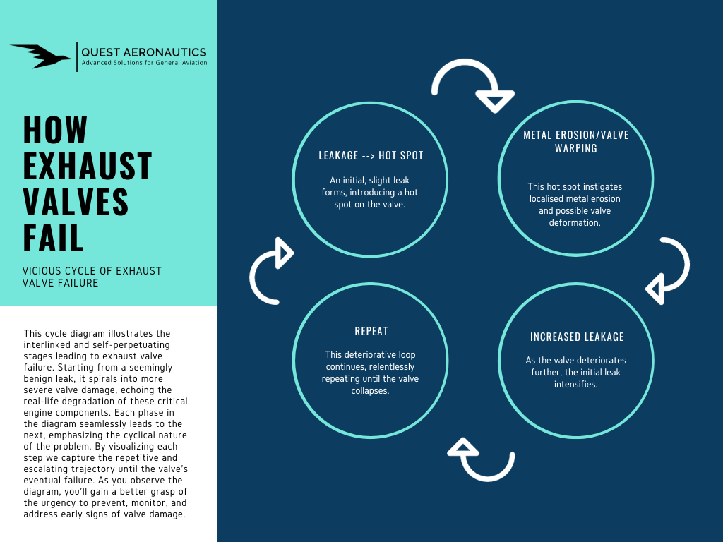
The demise of exhaust valves typically unfolds in a predictable, vicious cycle. Once a hot spot forms on the valve, its integrity is compromised. It’s not a matter of if it will fail, but rather when. Visualised briefly in the accompanying graph, this process can be distilled into four phases:
- An initial, slight leak forms, introducing a hot spot on the valve.
- This hot spot instigates localised metal erosion and possible valve deformation.
- As the valve deteriorates further, the initial leak intensifies.
- This deteriorative loop continues, relentlessly repeating until the valve collapses.
Why Exhaust Valves Fail
To ensure the optimal performance and longevity of your aircraft’s engine, understanding the potential causes of exhaust valve failures is essential. Here’s a breakdown of common issues that may arise.
Guide-to-Seat Concentricity
If not machined correctly, the valve guide might not be concentric to the valve seat. This issue can arise in new production or cylinders fresh from the rebuild/overhaul shop. The outcome is a leakage between the valve face and seat, leading to hot spots on the valve face.
Face-to-Seat Geometry
The valve face and seat’s geometry (angles) must perfectly fit. This ensures the contact area between the exhaust valve and seat is small enough for adequate pressure to clear deposits, yet large enough to dissipate heat from the valve to the cylinder head and prevent excessive temperatures.
Worn Guides
Due to the high temperatures, no lubrication exists between the valve guides and stems, leading to normal wear. Combustion deposits on the valve stem result in accelerated guide wear (bell-mouthing), especially in Continental engines with softer valve guides. Excessive wear in the valve guide leads to misalignment between the valve face and the valve seat. Such misalignment can lead to leaks between the valve face and seat, creating hot spots on the valve face.
Valve Sticking
Deposits, primarily lead (II) oxybromide (Pb3O2Br2) stemming from tetraethyl lead (TEL) and ethylene dibromide, can form hard metallic layers on valve stems. These deposits might cause leakages between the valve head and seat, creating hot spots. An early sign of sticky valves is “morning sickness” – the cold engine runs roughly when cold but operates normally when hot. These symptoms must be taken seriously. A stuck valve can lead to disaster; if it’s stuck closed, the cam drive, especially the pushrod, may sustain damage. If it’s stuck open, the piston may suffer damage, and if the valve head gets trapped between the piston and cylinder head, can cause a catastrophic engine failure.
Exhaust Valve Rotation
Most aircraft engine exhaust valves are designed to rotate slightly each time they open. This causes even distribution of heat load and prevents deposit formation on the valve seat. A failure to rotate might stem from worn-out “rotator caps”, “rotocoils”, or rocker arm and can easily be fixed.
Trapped Air in Hydraulic Lifters
In Rotax engines, exhaust valve failures often stem from trapped air within the hydraulic lifters. These lifters serve not only to bridge the gap between pushrods and rocker arms but also act as dampers, ensuring the valves close gently. When air is trapped, the damping function is hindered, leading to what’s known as “Hammer Betrieb” or “Hammer Operation.” This forceful operation can cause the valve head to separate from the stem.
Note: Lycoming engines have a 50/50 heat sink rate between the valve seat and stem. This necessitates tight stem/guide tolerances to dissipate heat into the cylinder head through the stem. Consequently, Lycoming engines are more susceptible to sticky valves. In contrast, Continental engines have an 80/20 heat sink rate between the seat and stem, making them more susceptible to burnt valves.
Potential Consequences of Exhaust Valve Failures
Exhaust valve failures can lead to a variety of outcomes. Sometimes, these failures are detected during routine maintenance checks, such as a differential compression test. However, more severe cases can cause cylinder shutdowns, leading to a rough-running engine and power loss. With a 6-cylinder engine, you might retain 80% power, but with 4-cylinder engines, the retained power diminishes significantly. This situation can produce substantial vibrations, stressing both the pilot and the engine. And in the worst scenarios, these failures can cause extensive damage.
Collateral Damage
If stress becomes too intense, the valve head might detach from the stem. If this severed head gets trapped between the piston and cylinder head, it can shatter the piston. This complication can swiftly evolve into a catastrophic engine failure, necessitating an emergency landing.
Even if the consequences aren’t immediately dire, they can still be dangerous. For example, if metal fragments from the exhaust valve enter the exhaust system, and your aircraft has a turbocharger, these fragments can damage the turbine. This harm can disable the turbocharger, resulting in a significant power loss.
Best Practice
The optimal approach is to prevent exhaust valve failures from the outset. Implementing an engine condition monitoring system can help you spot potential issues, like a leaking exhaust valve, before they escalate into severe problems like engine failure.
How to Avoid Exhaust Valve Failures
While most exhaust valve failures result from design, production, and maintenance issues, pilots can significantly influence exhaust valve lifespan. A primary concern for pilots should be lead deposits. To address this, it’s essential to maintain combustion temperatures within the optimal range and operate with a lean mixture to ensure cleaner exhaust gases.
Ideal Combustion Temperature
Maintaining high combustion temperatures is pivotal for reducing lead deposits. This serves two primary functions:
- It accelerates the scavenging reaction, turning harmful lead oxide first into the less detrimental lead oxybromides and then into the benign gaseous lead bromide. If we can transform most of the lead oxide to lead bromide before the exhaust valve activates, deposit condensation remains minimal.
- Elevated combustion temperatures lead to higher valve stem temperatures, reducing the condensation of any remaining lead oxybromides in the exhaust gas.
In the cockpit, the best measure we have for exhaust valve temperature is the cylinder head temperature (CHT), not the exhaust gas temperature (EGT). While it’s crucial to avoid excessively high CHTs for optimal engine longevity, overly reduced CHTs aren’t beneficial. Low CHTs imply decreased combustion temperatures that hinder the lead scavenging process and encourage lead oxybromide deposits.
For minimising valve sticking, especially in Lycoming engines, aim to maintain CHTs within these recommended ranges:
- Continental: Up to 400°F, ideally between 350° – 380°F
- Lycoming: Up to 420°F, ideally between 350° – 400°F
Note: For aircraft with efficient cooling systems (like Cirrus and Diamond), subtract 20°F. For spark plug gasket CHT probes, add 40°F.
Lean-of-Peak Operation
Another crucial strategy for reducing lead deposits involves keeping exhaust gases clean and minimising unburnt combustion byproducts. Achieve this by operating the engine lean (preferably lean-of-peak) in all scenarios except during cold engine starts and full-power take-offs and climbs. Ensure aggressive leaning during taxiing and other low-power ground operations to maximise combustion cleanliness and temperature.
How to Detect Exhaust Valve Failures Before They Happen
Imminent exhaust valve failures demand immediate attention. By adopting straightforward precautions, you can detect these threats early on. An engine condition monitoring system provides comprehensive insights into your aircraft engine’s health. It’s essential for all piston-driven aircraft. While we’ve previously delved into engine condition monitoring, let’s focus on exhaust valve failures here.
Borescope Inspection
Regular borescope inspections stand as the premier defence against potential catastrophic engine failures. Use borescopes to peer inside the combustion chamber, observing the cylinder head, barrel, piston crown, and valves for anomalies. Always perform this inspection when removing spark plugs or whenever you suspect valve issues. Seek symmetrical patterns resembling pizzas or bullseyes on valve heads; these patterns suggest consistent temperatures without hot spots. Asymmetrical or green discolourations flag potential valve failures. The Aircraft Owners and Pilots Association (AOPA) offers an insightful poster detailing exhaust valve appearances (see below). Moreover, borescope inspections unveil your engine operation nuances. Thick deposits on valves and spark plugs typically hint at rich mixtures and unclean combustion.

Engine Monitor Data Analysis
Engine monitor data analysis serves as another crucial detection tool. Beyond its myriad benefits, it can spot potential exhaust valve failures. Specifically, monitor EGT values for each cylinder, watching for slow, rhythmic oscillations at a frequency of one to two and a half cycle per minute, spanning 30° to 60°F. While manual monitoring remains an option, algorithms and AI streamline this task. To simplify, consider subscribing to our engine monitor data analysis service. Regular reports will keep you informed, especially about looming valve failures, prompting timely borescope inspections. However, this method works primarily for rotating exhaust valves and excludes sticky valves.
Note: Cylinders valves rotate to evenly distribute heat on the valve head and maintain cleanliness. Non-rotating and sticky valves won’t appear in the EMU data due to their static nature.
Oil Analysis
Lastly, regular spectrographic oil analyses form your final safeguard. Many exhaust valve failures trace back to rapid valve guide wear. These guides, composed of high-nickel alloy, can be monitored for wear by noting nickel levels in the oil. While engine monitor data pinpoints specific cylinders, oil analysis signals broader issues, which can then be verified via borescope inspection.
Conclusion
Imminent exhaust valve failures present a significant risk to aircraft safety and demand our utmost attention. By adopting proactive measures, such as utilising an engine condition monitoring system, pilots and aircraft owners can ensure the optimal health of their piston-driven aircraft engines.
Regular borescope inspections offer a detailed glimpse inside the combustion chamber, allowing for early detection of abnormal conditions or potential valve failures. Monitoring specific patterns on the valve head through high-quality borescopes becomes crucial.
Furthermore, the power of engine monitor data analysis cannot be overstated. By meticulously examining EGT values and leveraging modern algorithmic tools, potential exhaust valve failures can be flagged, enabling timely intervention.
Oil analysis acts as the final guard. Through the detection of elevated nickel values, which are often a sign of accelerated valve guide wear, we can get indications of potential problems. When in doubt, a borescope inspection serves as a reliable method to validate suspicions.
About Quest Aeronautics
Quest Aeronautics is a state-certified engineering office for aviation, dedicated to shaping the future of general aviation by providing innovative and cost-effective solutions to enhance aircraft performance and operations. With a focus on CS/FAR-23 and experimental/amateur-built (E/A-B) aircraft, Quest Aeronautics provides a range of services including flight testing, aircraft operations and maintenance consulting, high-quality aviation products, and tailored support for E/A-B projects. Collaborating with industry-leading partners, Quest Aeronautics is committed to delivering unparalleled support and expertise to individuals and organisations in the general aviation market.
About Author
Sebastian, the founder of Quest Aeronautics, is a driven and enthusiastic individual with a passion for aviation. Before delving into aviation, he gained valuable experience as a chemical process engineer and laboratory technician. Sebastian holds a Master of Science in Engineering and a commercial pilot licence, with several fixed-wing aircraft ratings under his belt. He has also completed an introduction course for fixed-wing performance and flying qualities flight testing at the National Test Pilot School in Mojave, CA and is compliance verification engineer for flight.